Transformer ballast
Transformers which do not self current limit i.e pole pigs or potential transformer need to have external current limiting, this can be achieved by the use of inductors or resistors, we have gone down the inductor route. The picture below show our twin coil ballasts. It is made up of a standard EI core with a coil of thick wire wound around the two outside legs of the core.
The core laminates are 50mm by 50mm silicon steel. The core also has plastic spacers inserted between the E and the top I core. This is used to fine-tune the current limiting.
As there are two coils they can be wired in three ways.
i-One coil in series
ii-Two coils in series
iii-Two coils in parallel
With each different combination a different level of current control is achieved.
As there are two coils they can be wired in three ways.
i-One coil in series
ii-Two coils in series
iii-Two coils in parallel
With each different combination a different level of current control is achieved.
The picture on the right show the white plastic inserts much better the plastic spacer can be removed a little to alter the current through put of the ballst. The two long threaded rods on the top holds the I core to the E core.
Below are two pictures of the box that now houses the ballast and the switch and its entire wiring layout
Below are two pictures of the box that now houses the ballast and the switch and its entire wiring layout
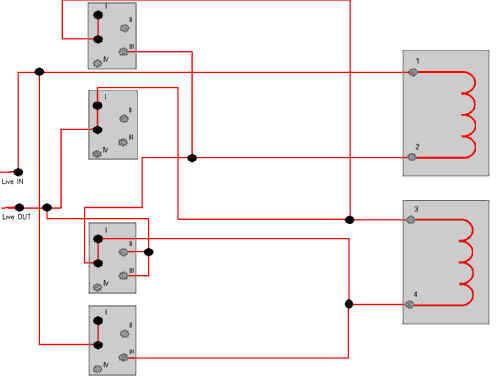
As you can see the wiring for the switch is quite complex and was arranged and built by Steve Bell, The switch is a 240vac/40A 4-pole, 4-way rotary switch, which was bought from display electronics. This system now does away with the arc welder that we were using before, and keeps all the wiring out of the way and reduces all the plugs and leads that we used before. With this switched supply we can limit form 7A (two coils in series) 16A (one coil) 32A (both coils in parallel), we tested the ballast with our new JACOBS LADDER.
Below is a wiring diagram for the switch.
Below is a wiring diagram for the switch.
Copy right 2021