3 coil Magnifier systems
The Magnifiing transmitter coil as Tesla called it was the main focous of his attention when he was still working on wireless transmission of electricty without wires in the late 1890`s, the magnifyer is now going to be our main focus as well.
The maganifyer has a driver system with is a primary and secondary that are very tightly coupled and are in a helix format this is fed from the normal tank circuit but uses a high speed/high break rate rotary spark gap, the output of the primary/secondary is fed via a transmission line (cable or pipe) to the extra coil, this is a base fed resonator.
Below are 3 of our driver coils,BMM1, BMM3 and the new BMM4
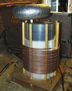
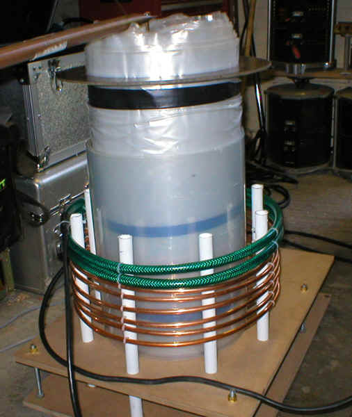

As you can see from above the primary to secondary coupling is very tight and need extra insulation between the two to prevent flash over, the hight to diameter radio also gets closer to 1:1 all the above coils have HD radios in the range of 1.8:1 to 1.14:1.
The BMM4 coil on the right uses a thicker primary conductor (12mm micro boar pipe), below are the spects of the BMM4 driver, Primary on the left and secondary on the right.
The BMM4 coil on the right uses a thicker primary conductor (12mm micro boar pipe), below are the spects of the BMM4 driver, Primary on the left and secondary on the right.
| Height | 8" |
| Diameter | 28" |
| Number of turns | 10 |
| Conductor diameter | 12mm |
| Primary to secondary distance | 3" |
| Height | 25" |
| Diameter | 22" |
| Wire | 12 AWG |
| Turns per inch | 11.7 |
| HD Ratio | 1.14:1 |
| Inductance | 28.18mH |
| Self capasitance | 25.77pF |
| Turns | 285 |
| Frequency | 186.74KHz |
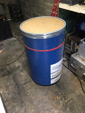
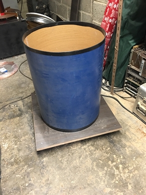
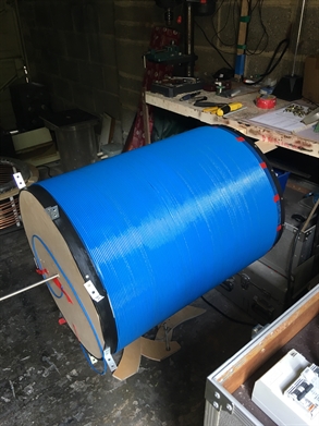
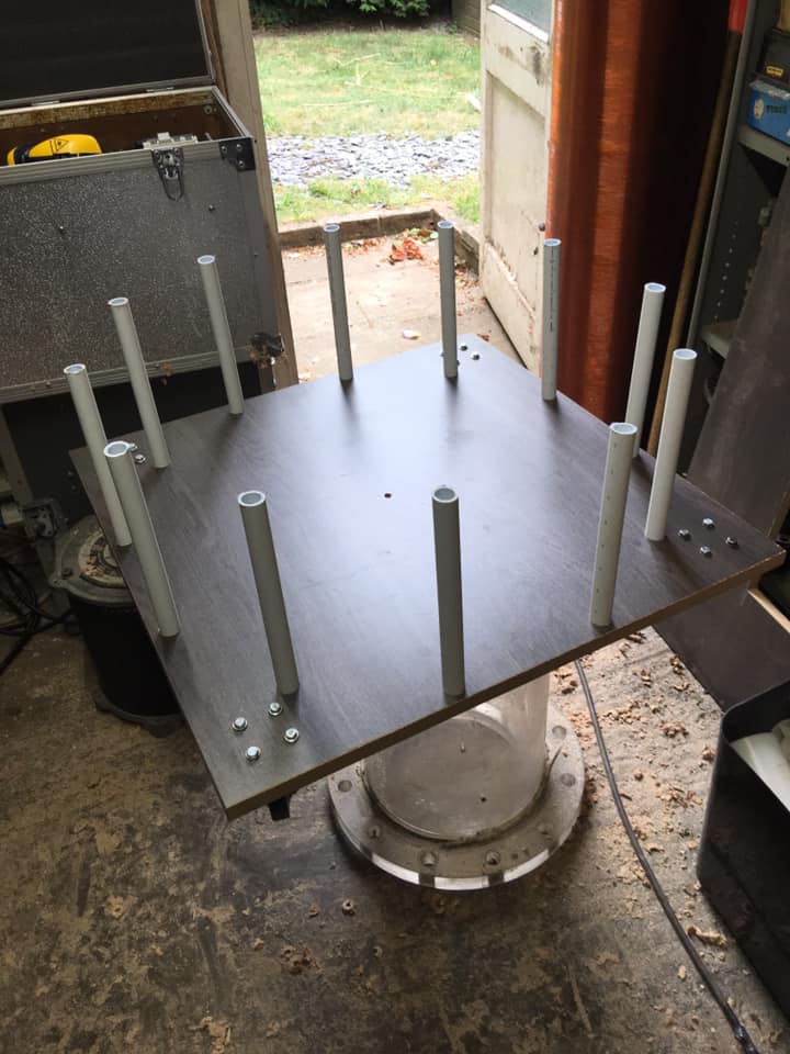
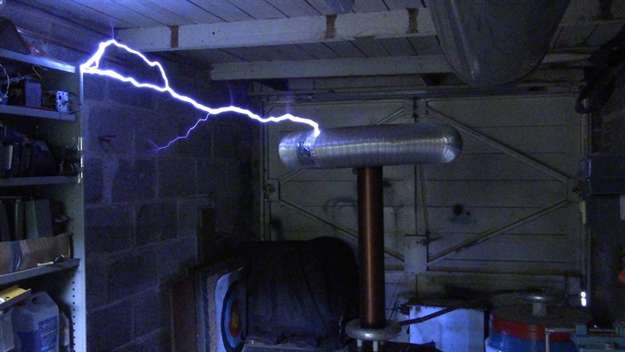
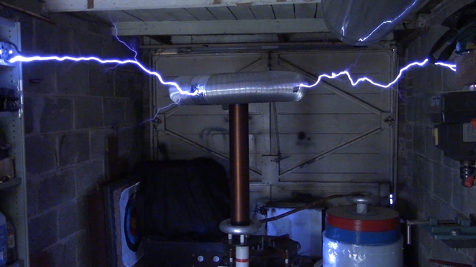
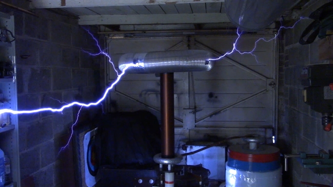
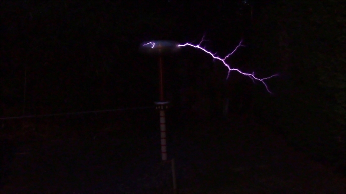
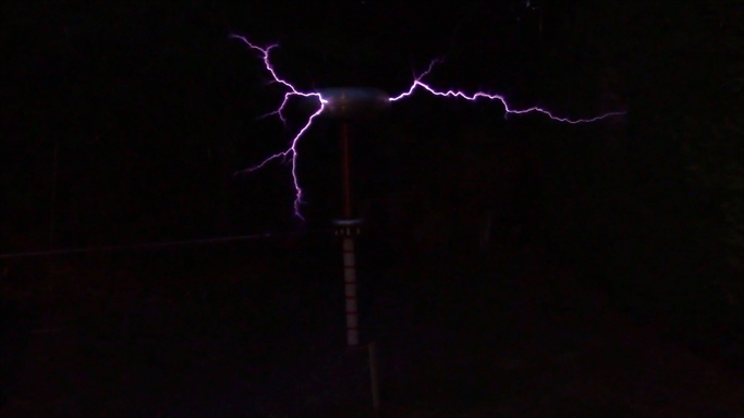
Next are a series of pictures showing some of the build process cutting down the plywood barrel then winding the 1640 feet of wire on to the formand a few pictures of the system being tested.
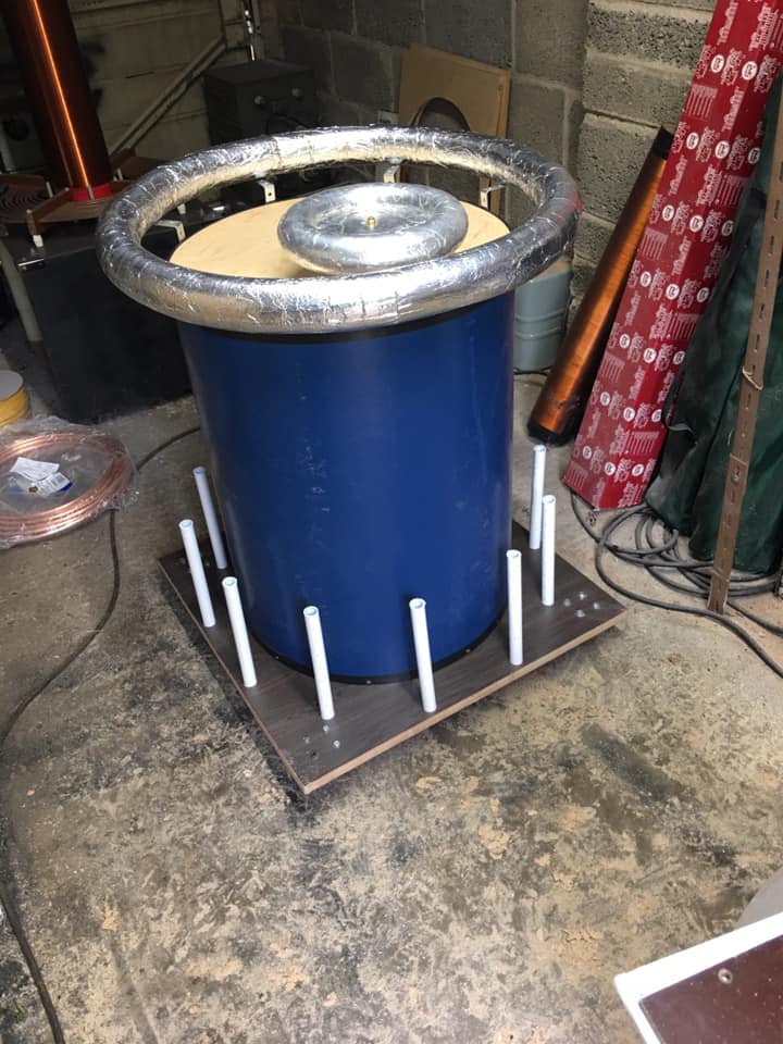
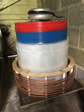
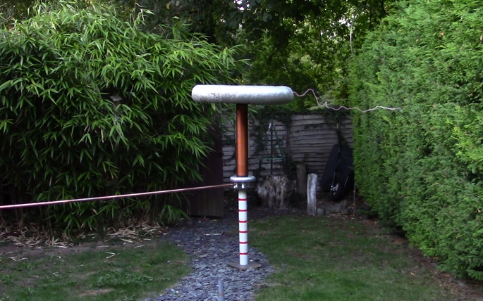
After the build with was time to test the system, it was hooked up too the new BM7 multy output base driver unit, the base unit can be switched from AC mode to DC mode quickly, the base driver uses the high speed series rotary spark gap, this first test was run using a break rate of between 411bps and 568bps then an outdoor test.
Copy right 2021